Breeze Designer
for Windows 4.0 and Windows 95
Draft: 28 September 1997
Version 2.0 User Guide
Breeze Designer Copyright 1994-1997 Neville Richards. All Rights Reserved.
THIS RELEASE SHOULD BE CONSIDERED A BETA RELEASE. THIS PACKAGE IS COPYRIGHT FREEWARE. NO RESPONSIBILITY IS TAKEN FOR ANY DAMAGE OR LOSSES CAUSED BY THIS PROGRAM. THIS PROGRAM AND ASSOCIATED UTILITIES ARE DISTRIBUTED AS IS, WITHOUT SUPPORT.
THIS PROGRAM AND ITS ASSOCIATED UTILITIES MAY NOT BE SOLD, OR DISTRIBUTED FOR ANY COMMERCIAL PURPOSES, WITHOUT PRIOR WRITTEN APPROVAL FROM THE AUTHOR.
PROGRAM DETAILS SUBJECT TO CHANGE WITHOUT NOTICE.
All trademarks belong to their respective owners.
Breeze Designer is a 32-bit 3D modelling and design tool for Windows NT and Windows 95. The program has been written to primarily interface with the Persistance of Vision (POV) raytracer, although there is support to export to a number of other popular renderers including Pixars's RenderMan.
Features
This program requires at minimum a 486-DX processor, and 8 megabytes of RAM, running Windows NT 3.5 or later, Windows 95. It is recommended to use a PentiumÒ based PC with 16 megabytes of RAM or 24 megabytes of RAM for Windows NT, with a display adaptor using 256 colour or greater video mode when running Breeze Designer.
To install Breeze Designer, first if necessary, unpack the shipping ZIP files into a temporary directory. Run the supplied 'Setup' utility from the from the temporary directory or an installation diskette if applicable, by selecting Run from the program manager File menu, or
taskbar then type A:\SETUP and return. The A: should be replaced by the directory containing the Breeze Designer installation files, as necessary. The setup program will allow you to select; the installation source directory, installation directory and the installed components to
be installed. These components include:
If you are using an external rendering package, such as POV Raytracer, it must be configured by supplying the appropriate settings in the Breeze Designer directory settings dialog. The renderer program name, include directory, and external image viewer program name are
required for Breeze Designer to execute an external renderer and/or image viewer. The following renderers are supported:
If you are upgrading from an earlier version, it is recommended to delete the old program and program setting files before installing this version. The program settings file may be found in the Windows directory.
If you are installing from one of the FTP site issues, make sure you have all the components, and they are named correctly. Please refer to the supplied README.WRI or README.TXT file for further information on the installation components and last minute changes.
In addition to these files a Breeze Designer SDK, and additional samples may be available. The SDK contains the Breeze Designer plug-in interface technical details, and a skeleton plug-in written in C.
Breeze Designer Win32s Installation (2.0.5)
Breeze Designer (2.0.5) includes limited support for Win32s, version 1.3. This allows Breeze Designer to be used with machines currently running Windows 3.11 with Win32s. There are a number of known problems with this release of Win32s and testing is on-going. It is hoped that fixes will be posted for these problems along with updates to Breeze Designer if there is demand for this configuration. The latest Win32s files may be found at:
ftp://ftp.microsoft.com/softlib/MSLFILES/PW1118.EXEWin32s 1.3 or later with OLE-2 support (above) must be installed before installing Breeze Designer. This support has been dropped from current releases due to development tool changes.
Breeze Designer Intel 3DR Installation
Breeze Designer includes support the Intel 3DR rendering library, version 2.1, for providing wire frame and shaded perspective previews within Breeze Designer. A complete Intel 3DR installation set is contained in the INTEL3DR.Z file. This contains an installation program which is run as part of the Breeze Designer installation when the Intel 3DR preview rendering option has been selected.
Intel’s 3DR version 2 requires the following software and hardware;
Minimum hardware requirements: An Intel486-DX 25Mhz processor based PC with 4 megabytes of RAM. Recommended hardware: A Pentium processor-based PC with 16 megabytes of RAM and an SVGA adapter supporting at least 256 colours installed in a PCI local bus slot.
The Intel 3DR rendering library can not be used concurrently with Windows NT OpenGL preview as Breeze Designer currently only supports one preview extension.
Currently the Intel 3DR rendering library IS NOT supported under Win32s. It has been tested under Windows NT and Windows 95.
Breeze Designer is a 3-D modelling and design tool for creating scenes for a number of ray tracing and rendering programs. Breeze Designer may also be used to develop simple key frame animation’s by combining a succession of scenes.
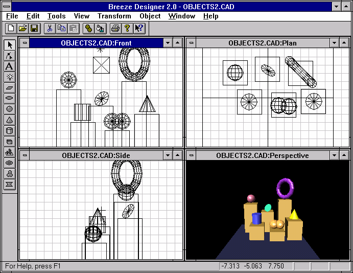
Breeze Designer provides a modeless modelling environment. Creating scenes, animation’s, and rendering may all done through the one Breeze Designer interface. Scenes are created by placing objects with the mouse
or keyboardKeyboard in front, side and plan construction views. A number of construction views may be used simultaneously for object placement. A preview window, showing the scene from the camera perspective, may be used during scene creation. The perspective view may be used to show the scene in wire frame or shaded views.There are a number of floating palettes, found under the Tools menu option. These may be used to select and edit objects, and to control the scene animation. These palettes may be left active at all times, allowing quick access to key program features.
A mouse or pointing device may be used to input co-ordinates in 3D directly into a scene. This is done by selecting points on or more scene views. As the mouse is moved over a view, the current 3D co-ordinate will be displayed in the status bar. Holding down the control key with the right mouse button pauses the co-ordinate tracking, allowing you to move from one view to the next retaining co-ordinates set in other views. Using this technique all three axis (X,Y and Z) may be input. Two axis are entered for each view. The center mouse button, if present, maybe used to clear the current 3D co-ordinate. The ‘Home’ key may alternatively be used. The perspective view does not generate mouse co-ordinates. The mouse can also be used to select multiple objectsgroups, by holding down the SHIFT key when selecting with the left mouse button.
To create a new object, select the object from the floating tools/objects palette, and then simply click on the desired 3D point in an appropriate view. Once an object is selected, by clicking on it or by selecting it from the ‘Object Selection’ palette, it may be moved in the current view by clicking on the object and dragging the mouse. Objects like text, torus, height-fields and lights are created with default properties. These properties may be changed, while the object is selected, once an object has been created by selecting the ‘Properties’ menu option or by pressing Ctrl+A.
The right mouse button is used to display a shortcut context sensitive menu.
Scaling objects
To change the size of an existing object double-click on the object (with the left mouse button), then use the sizing handles to alter the object size. If the SHIFT key is held during sizing the object will be sized proportionately.
Rotating objects
If the CONTROL key is held during the double-click, rotation handles will be displayed around the object, and the mouse may be used to set the object rotation.
If the mouse is used to perform a series of scale and rotation operations the object transformation matrix may become out of order. This means is the object is saved and loaded again, it may appear differently for how it was before the save. It is suggested to rebuild the transformation matrix by selecting the object properties and pressing OK. The object will be re-generated with a single transformation matrix. It is hoped that this problem will be fixed in a future release.
The keyboard may be used to manipulate objects or the camera view. The SPACEBAR is used in all modes to refresh or redraw the current scene.
The object controls are;
|
Arrow keys |
Move object |
|
+/- |
Scale object |
A special set of keys and mouse operations are defined for the
Point EditorpointeditGeneral keyboard accelerators:
|
Spacebar |
Refresh (or redraw) the current scene. |
|
Home |
Reset the 3D cursor position |
|
F11/F12 |
Zoom in and out, in the selected view |
|
Ctrl+A |
Select the object properties dialog |
|
Ctrl+T |
Select the textures selection dialog |
|
Ctrl+O |
Open a new scene |
|
Ctrl+S |
Save the current scene |
|
Ctrl-X |
Cut object to local clipboard |
|
Ctrl+C |
Copy object to local clipboard |
|
Ctrl+V |
Paste object from local clipboard |
Other Windows accelerators are as marked on the main menu.
The point editor allows you to create or edit point data sets. There are a number of special keyboard and mouse operations defined for this mode. These are;
|
<Mouse Left click> |
to select a point |
|
<Mouse Left click>+<Shift> |
to extend a selection |
|
<Mouse Left click>+<Control> |
to create a new point |
|
<Mouse Right>+<Ctrl> |
to pause co-ordinate tracking |
To move a point, with the mouse, click on the point and drag to the new location. If multiple
points are selected dragging a single point will cause all points to be offset the drag distance.
The following keyboard keys may also be used;
|
Arrow keys |
Move the selected points |
|
Delete |
Delete the selected point or points |
|
Keypad * |
Select single current point |
|
Keypad / |
Clear point selection |
|
Keypad +/- |
Select single next or previous point |
|
[ |
Select all points to the left (X-axis) from a selected point |
|
] |
Select all points to the right (X-axis) from a selected point |
Multiple objects may be selected dynamically by holding down the SHIFT key when selecting with the left mouse button. While the SHIFT key is being pressed, an unselected object will be selected into a group, a selected object will be de-selected. Once an object is selected it remains selected until, a new object is created, another unselected object is selected or the background is selected. Most operations are performed on the currently selected object or objects.
An object group may also be selected by clicking in a void region of the scene and dragging down to the right bottom corner. This will create a rectangular selection region. All objects in the final region will be selected when the mouse is released.
Simple groups of objects may be created by selecting a number of objects, an then selecting the "Group" menu option. To un-group selected grouped object, use the "Ungroup" menu option. Groups are only enforced at a logical level, all objects still behave as independent entities when moving, scaling or rotating. When a group is exported, the individual objects are declared in the exported scene and a new composite object is created containing all of the grouped objects. These composite groups are formatted to allow various CSG operations to be added manually. When blob objects in the same group are exported, they are automatically combined into one object.
CSG like operations may also be performed by using the object decompose feature. A solid object may be broken down into simple polygon mesh. The mesh can then be manipulated using the
transformationtransform tools to add, subtract or alter polygons within the mesh. Once a solid object has been decomposed there is no means of converting the resulting mesh back into a solid object. Also the properties menu will not operate on most mesh characteristics. The point edit tool allows decomposed objects to be manipulated node by node.The following diagram show the menu command structure of Breeze Designer under Windows 95 and Windows NT.
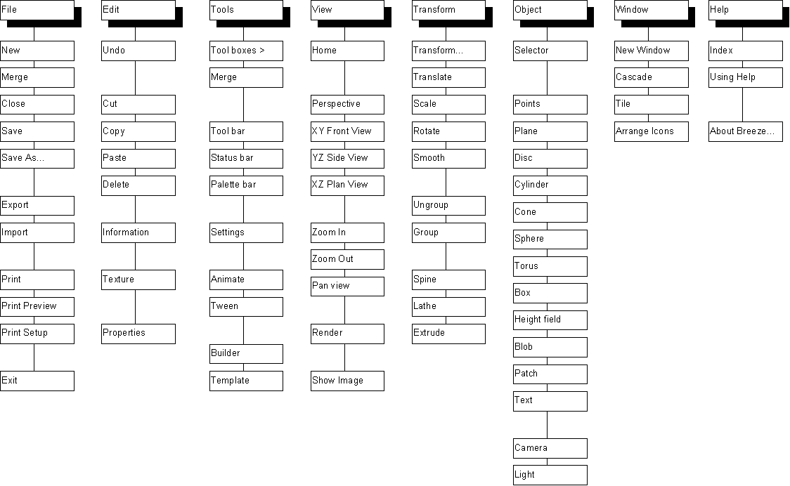
The File menu offers the following commands:
|
New |
Creates a new document. |
|
Open |
Opens an existing scene or macro. |
|
Close |
Closes an opened scene or macro. |
|
Save |
Saves an opened scene or macro using the same file name. |
|
Save As |
Saves an opened scene or macro to a specified file name. |
|
Import |
Import an object or objects in another file format |
|
Export |
Export an object or objects in another file format |
|
|
Prints a scene or macro view. |
|
Print Preview |
Displays the scene or macro on the screen as it would appear printed. |
|
Print Setup |
Selects a printer and printer connection. |
|
Exit
|
Exits Breeze Designer |
New
Use this command to open an existing scene in a new window. You can open multiple views of a scene at once. Use the Window menu to switch among the multiple open views.
You can create new scenes or macros with the New Command.
Shortcuts
Toolbar: ![]()
Keys: CTRL+O
Merge
Load an exiting Breeze Designer scene into the current scene.
Close
Use this command to close all windows containing the active document. Breeze Designer suggests that you save changes to your document before you close it. If you close a document without saving, you lose all changes made since the last time you saved it. Before closing an untitled document, Breeze Designer displays the Save As dialog box and suggests that you name and save the document.
You can also close a document by using the Close icon on the document's window, as shown below:

Save
Use this command to save the active document to its current name and directory. When you save a document for the first time, Breeze Designer displays the Save As dialog box so you can name your document. If you want to change the name and directory of an existing scene before you save it, choose the Save As Command.
Shortcuts
Toolbar: ![]()
Keys: CTRL+S
Save As
Use this command to save and name the active document. Breeze Designer displays the Save As dialog box so you can name your document.
To save a document with its existing name and directory, use the Save Command.
Import
Breeze Designer can import information from a number of different sources these include:
ASCII information may be imported as points, facets or objects.
Breeze will import both 2D and 3D AutoCAD DXF files. 2D files will be mapped onto the X-Y plane. Currently only 3D lines and facets are supported in 3D DXF models. All other attributes are ignored. Proprietary structures contained in AutoCAD release 13 and 14 created files are not supported.
The ASCII representation for points, is a list of X,Y and Z coordinates separated by commas, with one coordinate per line. Imported points may be used to create swept or lathed objects.
Export
Breeze Designer can export data in the following formats:
ASCII information may be exported as points, facets or objects.
The Breeze Designer export filters will produce a warning message if no lights sources have been created in a scene. To produce an image at least one light source should be in a scene. To automatically get a default lighting and camera setup, selected the ‘Use Default Scene Settings’ option in the options dialog. This will create two reference lights in a scene whenever the new button or file new menu option is used. Objects not directly (or currently) supported by some filters will be converted to polygon representations when output.
Persistence of Vision Raytracer is an excellent freeware ray tracer available for a number of platforms. This filter fully supports user defined textures, object groups and meta-shapes such as blobs. The smooth polygons setting should be set to export smoothed mesh objects for objects with pre-calculated smooth surface normals.
Breeze Designer supports a simple RenderManÒ RIB output filter. RenderMan objects such as patches and meshes, and use user defined textures are not currently supported. RenderMan RIB files should be sent as ASCII files when transferring files to Unix based platforms. The following statement is required by Pixar:
The RenderMan(R) Interface Procedures and Protocol are
Copyright 1988, 1989, Pixar
All Rights Reserved
RenderMan(R) is a registered trademark of Pixar
The VRML export filter currently writes version 1.1 compatible scenes. Light sources are exported as point and spotlight light sources. Texture mapping is supported for textures created with a VRML render profile. To add anchors (context sensitive jumps) or inline objects to existing scene objects, VRML information should be assigned using the objects extra data fields.
The "Neutral File Format" as defined by Eric Haines, and the AutoCAD DXF formats are supported as a basic geometry interchange formats. Textures are not output in either format.
Prints a scene or macro view.
Print Preview
Displays the scene or macro on the screen as it would appear printed.
Print Setup
Selects a printer and printer connection.
Exit
Use this command to end your Breeze Designer session. You can also use the Close command on the application Control menu. Breeze Designer will prompt you to save scenes or macros with unsaved changes.
Shortcuts
Mouse: Double-click the application's Control menu button.

Keys: ALT+F4
The Edit menu offers the following commands:
|
Undo |
Reverse previous editing operation. |
|
Cut |
Deletes an object or objects from the scene and moves it to the clipboard. |
|
Copy |
Copies an object or objects from the scene to the clipboard. |
|
Paste |
Pastes an object or objects from the clipboard into the scene. |
Undo
Not currently implemented. [This feature will be complete in the final version]
Cut
Use this command to remove the currently selected object from the scene and put it on the clipboard. This command is unavailable if there is no object currently selected.
Cutting data to the clipboard replaces the contents previously stored there.
Shortcuts
Toolbar: ![]()
Keys: CTRL+X
Copy
Use this command to copy selected object onto the clipboard. This command is unavailable if there is no object currently selected.
Copying data to the clipboard replaces the contents previously stored there.
Shortcuts
Toolbar: ![]()
Keys: CTRL+C
Paste
Use this command to insert a copy of the clipboard contents at the insertion point. This command is unavailable if the clipboard is empty.
Shortcuts
Toolbar: ![]()
Keys: CTRL+V
Delete
Use this command to delete the currently selected objects.
Information
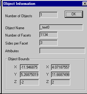
The information dialog contains details about the selected objects. This information includes the number of selected objects, object names, the number of polygon facets, sides per facet, object attributes and the bounding region for the selected objects.
When multiple objects are selected this information will reflect the summed properties of all the selected objects. In this way the bounding area of a given number of objects may be calculated.
Texture
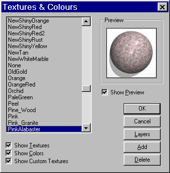
The texture selection dialog, allows you to pick an existing colour or texture from a list. A preview image, of each texture, is also available. To add a new texture, press the Add button. This will allow custom textures to be built from a selection of characteristics. Texture samples may be either Targa or GIF images. Each sample image is 100x100 pixels. Targa images are best suited to high-colour displays, as they provide the most accurate preview. For 256 colour displays, GIF images are recommended. This may increase the delay between viewing each image as GIF files are decompressed prior to viewing. This format does however save the most disk storage.
To add a new custom texture, display the texture selection dialog, and press the Add button. This will enable the texture builder dialog. The texture builder allows you to modify an existing texture, by specifying a parent texture as a template, or you may create a new texture from scratch. When an existing custom texture is selected the Add button will show Edit to allow the texture to be changed.
To add new textures to the texture selection list, without creating textures, hold the control key while pressing the add button. This will allow you to add to the texture list. This should only be used to add existing textures.
When using POV-Ray as the renderer, textures may be layered. Press the layers button then enter and enable the textures in order you wish to layer. Only texture names should be used. If a texture is selected when the layers button is pressed it will be added to the next available layer in the layers dialog. [This is a new feature and may be revised before release]
Properties
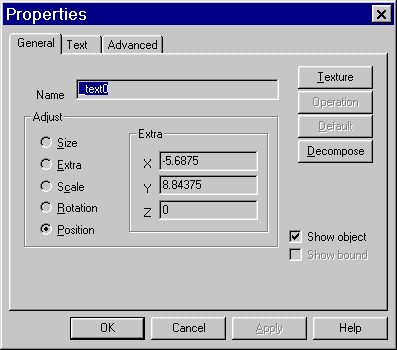
The object properties dialog is used to change the various properties associated with an object. Information not entered when an object is created may be added with this dialog. This particularly applies to text, light, height field and torus objects. The height bitmap can be found and added to a height field, as well as the water level and torus minor diameter (Size Y) through the properties dialog.
Adjust the object parameters for size, scale, rotation, position and object specific settings.
Apply and Ok regenerate the selected objects or objects with the current settings.
Texture selects a texture to apply to the selected object.
Operation selects a CSG operation of union, merge, intersection, or difference for the objects group.
Decompose solid objects into a polygon mesh. This operation is permanent. The resulting polygon mesh may be manipulated or used as components by the point and polygons transformation options.
Find File locates an image file to be used with a height field object.
Font selects a font type and size to be used with a text object.
When transferring scenes containing text objects from one machine to another the TrueType source font should also be available on both machines. If the original text font is not available Breeze Designer will attempt to select the closest available font. The resulting scene may not be desirable. Font styles such as bold, italic and underline are not currently supported.
Tool boxes
Toolbar
![]()
The toolbar is displayed across the top of the application window, below the menu bar. The toolbar provides quick mouse access to many tools used in Breeze Designer,
To hide or display the Toolbar, choose Toolbar from the Tools menu (ALT, T, T).
Click To
![]() Open a new document.
Open a new document.
![]() Open an existing document. Breeze Designer displays the Open dialog box, in which you can locate and open the desired file.
Open an existing document. Breeze Designer displays the Open dialog box, in which you can locate and open the desired file.
![]() Save the active document or template with its current name. If you have not named the document, Breeze Designer displays the Save As dialog box.
Save the active document or template with its current name. If you have not named the document, Breeze Designer displays the Save As dialog box.
![]() Print the active document.
Print the active document.
![]() Remove selected object from the scene and stores it on the clipboard.
Remove selected object from the scene and stores it on the clipboard.
![]() Copy the selection to the clipboard.
Copy the selection to the clipboard.
![]() Insert the contents of the clipboard at the insertion point.
Insert the contents of the clipboard at the insertion point.
![]() Reverse the last editing. Note: You cannot undo some actions.
Reverse the last editing. Note: You cannot undo some actions.
Status bar
![]()
The status bar is displayed at the bottom of the Breeze Designer window. To display or hide the status bar, use the Status Bar command in the Tools menu.
The left area of the status bar describes actions of menu items as you use the arrow keys to navigate through menus. This area similarly shows messages that describe the actions of toolbar buttons as you depress them, before releasing them. If after viewing the description of the toolbar button command you wish not to execute the command, then release the mouse button while the pointer is off the toolbar button.
The right areas of the status bar indicate which of the following keys are latched down:
Indicator Description
CAP The Caps Lock key is latched down.
NUM The Num Lock key is latched down.
SCRL The Scroll Lock key is latched down.
Palette bar
TODO
Settings
General Settings
The options dialog controls the user definable settings of the Breeze Designer program. Push buttons on this dialog additionally allow the user to define the view, rendering and plug-in module settings.
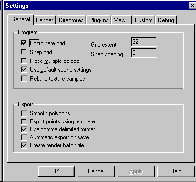
Coordinate Grid, Grid extent, Display and set the extent of the visible coordinate grid which is shown about the origin.
Snap Grid Set, Snap spacing set the snap grid distance, zero disables the snap grid. The snap grid is used when creating objects, and when moving objects with the keyboard.
Use Default Scene settings A default scene including the two lights sources of created for a new scene.
Place Multiple Objects or place a single object once selected, then return to the select state.
Rebuild texture Samples Enable texture rebuild options, found in the Texture dialog.
Smooth Polygons Automatically generate smoothed polygons for all polygonal objects in the exported scene. This option may the slow scene exports, and should only be used for final generation. Individual objects may be smoothed with the Transform/Smooth menu option. Objects already smoothed will not be affected by this option.
Export Points using Template enables point arrays to be exported using an assigned template
.Automatic Export on Save An exported version of a scene will be created each time the scene is saved.
Create Render Batch File A batch file is created to render the exported scene.
Render Settings
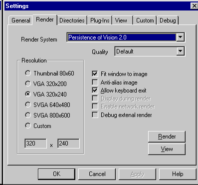
Breeze Designer supports both and internal rendering systems and external rendering package. This is selected through the Render and View settings dialog. Images may be rendered internally up to 4096 x 4096 (or constrained by available memory). A number of pre-set resolutions are available.
From within the render and view settings dialog, if selected, the external rendering package and image viewing package can be executed using the current dialog settings.
The image output quality is also set through this dialog. Higher quality output generally requires more calculation time and or more memory. Available image qualities of Default, High and Low are available. The high setting will automatically enable the maximum quality renderer options, which may include super-sampling and anti-alias settings.
Directory Settings
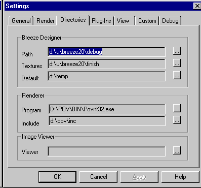
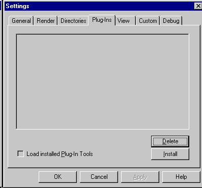
Breeze Designer has support for "Plug-In" modules. This allows the basic interface to be modified and added to by third party utilities. The Breeze Plug-In API is available in the Breeze Designer Plug-In Programming Guide. At this stage this interface is specific to Breeze Designer and may only be used with Breeze Designer compatible plug-in’s.
To add a new plug-in select "install" from the Plug-In setup dialog, then select the new plug-in file. This will be added to the Plug-In setup list. The "Load installed plug-in tools" option, found on the main options dialog should be checked for Breeze Designer to load the installed plug-in’s next time it is run.
The beta version of Breeze Dsigner includes a number of built in Plug-In modules, these are:
Points For generating simple point sets, including; lines, circles, parabolas, and helix data sets.
Polyhedra For generating a variety of regular multi-sided shapes. Also called SHAPES.
Objects For generating a selection of objects including; cables and screw threads.
Other Pug-In’s are added to the Breeze’s generate menu. Currently the following Plug-in modules are in development;
Creatures This plug-in uses creates a data hierarchy for creating and animating articulated figures. Creatures can be created with a number of limbs, and manipulated through setting limb angles or via a high level creature script.
** INCOMPLETE **
Particles A particle system simulation, used for creating particle effects or for co-ordinating large number of discrete objects.
** INCOMPLETE **
View Settings
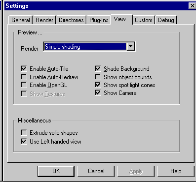
Breeze Designer supports a number of methods for displaying a simplified preview of the final rendered image in the prespective or camera view. There are three built-in methods for displaying shaded objects in the preview window.
The OpenGL option supports fully shaded, and texture mapped options for preview generation.
Render Select the render mode used for displaying previews in the perspective view. The default "None" shows a wire frame view, while "Simple shaded" shows a quick full color preview and "Textured shaded" show a preview using image mapped textures.
Enable Auto-Tile (default ON) Automatically tiles the views as each is created. Deselect this option to allow user positioning of each view.
Enable Auto-Redraw (default ON) By default Breeze Designer redraws all scene views after every operation. This can be disabled for working on large scenes by deselecting this option.
Shade Background (default ON) Use the scene background color when displaying views.
Enable OpenGL or Enable Intel-3DR options to enable or disable using the OpenGL or Intel-3DR sub-systems to display the perspective (camera) view depending on the preview engine installed.
Show Textures Use texture maps when using OpenGL to display preview. This option is disabled is the texture maps or texture map configuration file or not found.
Show Camera Display the camera as an object within the scene.
Show object bounds displays the object boundary, as a rectangular region, instead of the object mesh representation. This allows faster screen updates for complex shapes. (Only a limited set of objects may be shown as bounds in this release).
Show spot light cones displays object queues for the spot light target point & light cone. This option effects only objects created after this option is selected or delselected.
Extrude solid shapes enables end caps for extruded shapes.
Use Left handed view Used to switch view point Z axis direction. By default Breeze Designer defines the positive Z axis as the one coming out of the screen.
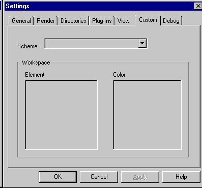
Custom Settings
Animate
Tween
Builder
The object builder may be used to create a variety of objects and data sets. These objects include cables, screw threads, a variety of polyhedral shapes and a points sets describing a line, circle, helix and parabola.
Template
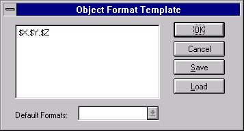
The object format templates can be used to control the conversion of point data sets into object sets, when a scene is saved. This feature can be used to allow large collections of objects to be controlled through point set manipulation.
The sequence template is used when creating a sequence file for an animation. The sequence files may be used as batch files to perform special manipulation, such as combining a set of scene files specific to an animated scene.
The following variables can be used within templates:
$X The current X coordinate
$Y The current Y coordinate
$Z The current Z coordinate
$N Current file or project name
$E Current file extension
$F The current animation frame number
$R The selected external renderer
$I The selected render include path
$W Selected render with
$H Selected render height
When writing sequences, the sequence list may be written in temporal distribution order. This order will allows animation to be checked using the least number of frames. The most statistically significant scenes will be written first in this sequence.
Home
Reset the current scene views to the Breeze Designer default settings.
Perspective
Display a perspective view of the current scene. The perspective view can not be edited.
XY Front View
Display a front view of the current scene.
YZ Side View
Display a side view of the current scene.
XZ Plane View
Display a plan or top view of the current scene.
Zoom in
Zoom in on the current view (Also F11).
Zoom out
Zoom out on the current view (Also F12).
Pan view
Switch the current view to pan mode. In this state the view can be panned by clicking down in the view and dragging away from the direction you wish to go. Once the mouse is released the view will revert to edit mode.
Render
TODO
Show Image
TODO
Transform
The transformation tools are the Breeze Designer object data manipulation starting point. From within transform tools you may sort, flip, filter, normalize, center, enlarge, reduce and fix any polygon based object.
Sorting will sort points by X, Y and Z values respectively.
Flip may be use to transpose points, swapping Y and Z, X and Y, X and Z or mirror X, Y and Z about the origin. These functions are useful for re-orienting models created in other coordinate systems.
Normalize is used for resetting polygon collections for manipulation within Breeze Designer. By default all operations within Breeze Designer are assumed to be about the center of an object. Data imported into Breeze Designer will have the origin as the center. By normilizing an object, the center is calculated and the polygon data is re-computed about its origin then offset within the scene.
Centring will re-compute the object data about the origin.
Enlarge and reduce will expand and reduce the selected object by a factor of two respectively.
Fix polygons checks and recalculates the surface normals for imported smoothed objects. All surface normals will be reset to unity values ie within a 1 unit sphere. The normal orientation will be reset for Breeze Designer.
Translate
Scale
Scale will scale an object or objects by the selected amount in the X, Y and Z axis. When uniform scaling is selected the X value will be used for all axis. Enlarge and reduce x2 will enlarge and reduce the selected object uniformly by a factor of 2. Apply will apply the current scale setting immediately. If Apply and Ok are used consecutively the scale operation will be applied twice. Objects are scaled about their center, when scaling multiple objects they are scaled about the center of the selection. Objects may be scaled by the mouse by double clicking on an object then dragging the scale handles.
Rotate
Rotate will rotate an object or objects by an angle in degrees about the X, Y and Z axis. Objects are rotated their center, when scaling multiple objects they are rotated about the center of the selection. Objects my be scaled by the mouse by double clicking on an object while holding control then dragging the rotate handles.
Smooth
Smooth will compute the surface normals for a polygon object to achieve a smooth
appearance.
Hide
Hide removes an object from any of the views. The object will still be exported for rendering. Objects can be unhidden by selecting them in the select object palette and re-selecting hide.
Align
After selecting multiple objects, they may be aligned top to bottom, left to right or front to back. All objects are aligned about their center. The first selected object on the select object palette will be used to determine the reference value to align against.
Ungroup
TODO
Group
Combine a group of selected objects into a logical group.
Spline
TODO
Lathe
TODO
Extrude
TODO
Objects are created 1x1x1 unit (mostly) by default. Simple objects can be scaled to suit. Objects that have multiple elements, such as a torus can be adjusted through the object properties dialog (Ctrl+A).
Selector
Select and delselect one or more objects.
Points
Create or edit an object containing a list of points. A special set
of keyboard and mouse operations are defined for the p
Plane
Create an infinite plane in the X,Y or Z axis.
Disc
Create a 2D disc object.
Cylinder
Create a 3D cylinder object.
Cone
Create a 3D cone object.
Sphere
Create a 3D sphere.
Torus
A torus is a 4th order quadratic polynomial shape that looks like a donut or
inner tube. The torus is defined tohave two radii, a major and minor. The major
radii defines the centre of the outer (or larger) ring, while the minor defines
the radius of the cross
Both these settings can be adjusted using the size property, on the object properties
dialog (Ctrl+A). The X value is the major radii while the Y value is the minor radii.
Box
Create a 3D cube.
Height field
Height fields are fast, efficient objects that are generally used to create mountains
or other raised surfaces out of hundreds of triangles in a mesh.
A height field is essentially a 1 unit wide by 1 unit long box with a mountainous surface on top. The height of the mountain at each point is taken from the color number (palette index) of the pixels in a graphic image file.
Height fields are created from image files. Use the object properties dialog to select a Targa, GIF, POT or JPEG image to associate with a placed height field. The water level (darkest color shown) may also be adjusted by using the Y parameter of the water level field, in the properties dialog.
At this stage height fields are only exported to POV-Ray scenes. Height fields are shown as a pyramid object within Breeze Designer. The peek of the pyramid represents the top of the height field. The final mesh is computed by POV-Ray when the scene is rendered.
Blob
Create a meta-ball "blob" object. Blobs should be grouped for an interaction
surface to be created. The X threshold value controls the interaction threshold.
Patch
TODO
Text
Create a text object. Once the object has been placed the actual text displayed text may
be added through the properties dialog. The properties dialog (Ctrl+A) also allows a True Type font to be selected. A text objects are converted into a mesh before rendering. Some font attributes are not supported by the font geometry generator.
User defined
TODO
Camera
The camera settings are used when creating an exported scene to define the observer, viewpoint, field of view and view aspect ratio. When using OpenGL the camera position is used to place the perspective view observer and viewpoint.
Track Position, Track View Point and Attach allow the camera to by moved by, or to follow, a point sequence when the camera object has been animated.
Light
TODO
The Window menu offers the following commands, which enable you to arrange multiple views of multiple documents in the application window:
|
New Window |
Creates a new window that views the same scene. |
|
Cascade |
Arranges windows in an overlapped fashion. |
|
Tile |
Arranges windows in non-overlapped tiles. |
|
Arrange Icons |
Arranges icons of closed windows. |
|
Window 1, 2, ... |
Goes to specified window. |
New window
Creates a new window that views the same scene.
Cascade
Arranges windows in an overlapped fashion.
Tile
Arranges windows in non-overlapped tiles.
Arrange Icons
Arranges icons of closed windows.
The Help menu offers the following commands, which provide you assistance with this application:
|
Index |
Offers you an index to topics on which you can get help. |
|
Using Help |
Provides general instructions on using help. |
|
About |
Displays the version number of this application. |
Index
Offers you an index to topics on which you can get help.
Using Help
Provides general instructions on using help.
About
The current program release information may be found on the About dialog. Resource information specific to the current operating environment will also be displayed.
Breeze Designer supports a number of floating tool palettes. These once selected remain in screen and may be used in conjunction with the mouse and menu operations.
The toolboxes may be moved and placed on the screen as desired. Once moved their position is retained from one session to the next.
The tool palette allows basic scene objects to be created quickly, by simply selecting the type of new object, then clicking on the desired 3D point. To modify an object once is has been created, use the move, scale, rotate buttons or the properties dialog option or add a surface finish by using the texture dialog.
![]()
To add a texturetextures to an object, press Ctrl+T keyboard accelerator. This will allow you to select the object colour or texture from a list of pre-defined textures, or you can create a new texture interactively.
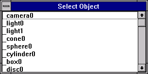
The object selection palette shows a list of all the current objects in the scene. Objected may be selected by highlighting the an object and pressing the select button. The Edit and Delete operations are performed on the currently selected object or objects.
Breeze Designer supports an unlimited number of objects. The maximum number of objects is limited only by the amount of memory available under Windows. As all objects are on a common layer, the speed of adding, deleting and manipulation objects will decrease as more objects are added.
TODO
Breeze Designer may display an thumbnail image showing a sample of a selected texture. The texture sample images are created by rendering a small sample scene for each of the available textures. A full set of standard texture sample images may be installed when installing Breeze Designer. When new custom textures are created an option is presented to render the new texture. This process will create a new sample image for the custom texture.
To create sample images for any missing texture sample images, select the "Rebuild Texture Samples" from the program settings dialog, and select "Rebuild" from the texture selection dialog. Selecting "Rebuild Texture Sample" will enable two options in the texture selection dialog, "Rebuild" and "Reset Colours".
The "Rebuild" option will create a series of render files, one for each texture sample not present in the selection list. A batch file called TEXTURE.BAT will also be created in the defined textures directory. The batch file will render each texture image. Make sure the renderer directories are set correctly before using this option. This option also rebuilds and compacts the custom texture database.
The "Reset Colours" option will rebuild the quick render colours used by the internal preview renderer, and the OpenGL preview options. These options may take some time on slower machines.
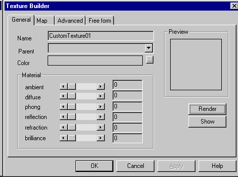
Breeze Designer texture builder allow you to create new custom textures. The texture builder is controlled by the render configurations, and so textures created for one renderer are not transferable to another. The texture builder includes a freeform tab which shows a preview of the texture procedure built within the builder. This procedure may be copied (Ctrl+C) to the clipboard for use in other programs. The freeform edit will also import textured (.INC) created by other programs.
Name for the custom texture. Each new custom texture must have a unique name.
Parent specifies the base texture used to the new texture (optional).
Color specifies the texture color (optional).
Image map specifies an image map file (optional).
Ambient, Diffuse, Highlight, Reflection, Refraction, Transparency set the various basic optical properties for the defined texture.
Render executes the selected external renderer, to create a sample image.
Show displays a rendered sample image. If an image has been rendered previously it will be displayed automatically.
Advanced allows renderer specific texture attributes to be selected, and or altered.
When using the "Advanced" settings to create or modify a texture, the texture attributes are broken down into families of attributes. These families are described as items and are pigment, normal, finish, modify and freeform. The freeform group allows textures to be entered as the will finally appear to the renderer, bypassing the other texture options. To select a specific attribute use the item field to select attribute group then option. For example to set the "Phong" value of a texture, select the "finish" item then select "Phong" from the options, enter the value and check the "Enable" option. Alternately the "highlight" slide may be used to set the "Phong" value.
If you wish to create a preview sample of the new texture, before pressing the ‘OK’ button, press the ‘Render’ button to create the sample and the ‘Show’ button to view it when rendered. The ‘Render’ and ‘Show’ buttons may be used a number of times in the texture design phase to fine tune the texture appearance.
New textures created will be added to a local database, so that they can be shared among a number of scenes. The texture information for the current scene is also exported within Breeze Designer scene files. All texture names must be unique. Currently there are no rules to control correct semantic texture structure. The texture builder will allow conflicting attributes to be used within the same texture.
Breeze Designer supports a simple key frame animation system. Other third party animation tools may be implemented via
Plug-In module support.Animation dialog
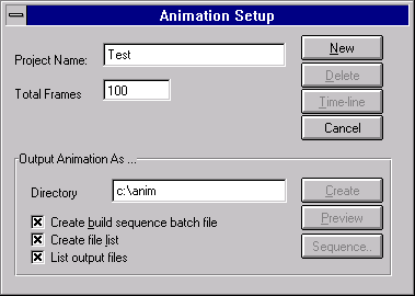
New creates an animation sequence or sub-project, using the project name and total frames.
Project Name sets the name for the current animation sequence or sub-project. This name should be less than 8 characters if the animation is created on a disk that does not support long file names. Each scene from the animation will be named using the project name as the base name, with the current frame appended.
Total Frames sets the maximum number of frames in the current animation.
Time-line (disabled)
Create builds and writes to disk the current animation. The animation is written as a series of scene files, with additional support files, if selected. These files are written to the specified output directory.
Directory specifies the output directory when writing the completed animation frames and support files. If no directory is specified the current directory will be used.
Create build sequence batch file writes a file using the sequence template. This may be used as a batch file to create the final animation.
Create file list creates a list containing all of the frame files written for the animation. This may be useful when assembling the rendered scenes into the final animation.
List output files lists the rendering output file names, ie FILE#.TGA in the file list. By default the rendering input file names are listed.
Preview [currently disabled]
Sequence allows the output sequence template to be selected, and or edited.
Tween Dialog
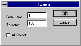
Tween may be used to generate in-between frames between nominated start and end frames for the current animation. Position, scale and rotation are all interpolated when generating the in-between frames.
Animation Control palette
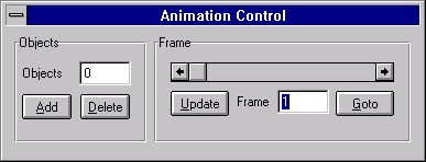
Add. The "Add" button will promote the currently selected objects for animation. To add a motion path to an existing animated object; selected the desired object, and a point series that describes the required motion, and press the "Add" button.
Update. Key frames are created by moving the a frame, and pressing the "Update" button. This will acquire the current object attributes, and set them to the current frame. To see an animation frame; use the slider to move the required frame, or enter the frame press the "Goto Frame" button. The current scene will be re-drawn to show the selected frame.
When an animation sequence is created, a series of render scene files are created. One scene file per frame. A sequence file and a frame list may be also created. The sequence file entries are created by parsing the current sequence
template. These entries may be in distributed temporal order. Distributed temporal order will attempt to create the most complete animation from the minimum number of frames. The sequence file may be used as a batch file to run the render process. The frame list is a simple list of all the render scenes created in time order.